Kato Turnouts Wiring Diagram
Kato Turnouts
Unofficial Ttrak Handbook Small Modules For N Scale Railroads

Question Proper Wiring Of Kato 6 Turnouts In Dcc Dcc
How To Make Kato Turnout Controls N Scale Model Trains Fifer
Kato Unitrack Basic Question Turnout Accessories Model

Wiring For Dcc With N Scale Kato Unitrack Youtube

The ds51k1 is designed specifically for kato n scale turnouts.
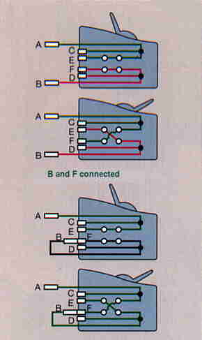
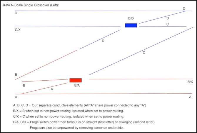
Kato turnouts wiring diagram. Wiring this set of turnouts is identical to wiring the individual turnouts as described at the top of this webpage. In cases where there are two turnouts in a crossover track arrangement you must use two ds51k1s each assigned to the same address installation of the four decoder wires requires soldering skills. This is a 4. I do not do any thing special or make any modifications to run dcc on unitrack.
Conventional wiring wisdom holds that power should be fed to a turnout the kato switch es as labelled in your diagram at the toe end the single track end not the heel end the 2 tracks diverging end as shown your single power feed is feeding both turnouts via the heel end and only on one track the main. By utihzing the kato turnout control switches for your remote. Sometimes wiring diagram may also refer to the architectural wiring program. The simplest approach to read a home wiring diagram is to begin at the source or the major power supply.
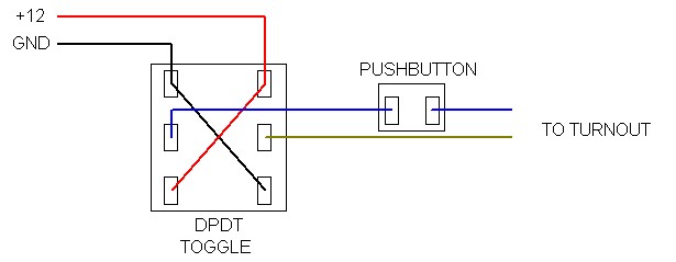
Using a unique keyed plug socket system kato power pack also provides simple connection to the kato turnout control switches 24 840. Halloween 2012 video tackles lighting the underside of your layout wiring a kato switch with toggle switches and make a small control panel for my alleghany industrial district. The kato unitrack n scale turnouts are different than the ho. Kato manufactures both a 4 and 6 turnout.
Please limit them to one. Wiring for dcc with n scale kato unitrack. Please send us your topics for video ideas.

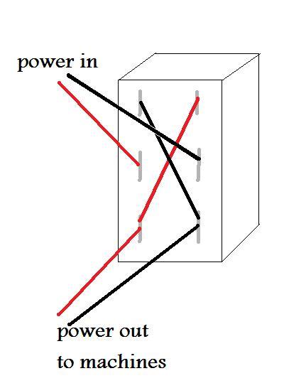
Single Coil Switch Machine Driver
Dcc Compatible Turnouts Dccwiki
Tomix Turnout Control System

Turnout Control Switch Kato 24 840 N Scale
Dcc Basics Wiring A Layout For Dcc Power

Is It Really Easy To Add Indicator Lights To Kato Turnouts Or Am
Mini Toggle Switches And Unitrack Trainboard Com The

Loop Wiring Diagram For Ac Or Dcc With Images Model Trains
Https Encrypted Tbn0 Gstatic Com Images Q Tbn 3aand9gcsafbyalhamok2yjity81kh3t3vljxiskxps32lj Jexooqbj J Usqp Cau

A Few More Unitrack Turnout Wiring Questions Dcc Electrical
Switches Etc

Team Digital Smd2 And Kato Unitrack Switch Machine Application Info

Euro Rail Hobbies And More Blog Using Esu Switchpilots For Bi
